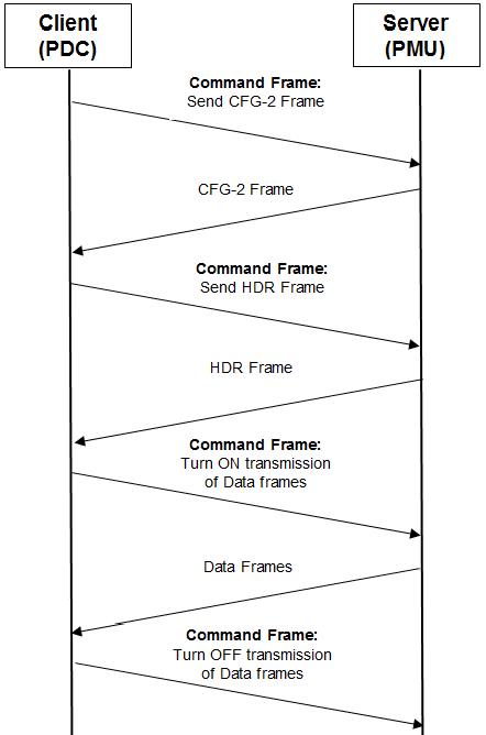
Figure 1. Sequence diagram between a PMU and a PDC
Communication between a PMU (Phasor Measurement Unit) and a PDC (Phasor Data Concentrator) takes place under the Client-Server scheme where the PMU, which provides the data, acts as the Server and the PDC, which requests, receives and processes the data, acts as the Client. The sequence diagram shown in figure 1 describes a simple communication process between a PMU and a PDC. In this diagram it is assumed that all transmitted frames are correct, i.e. no frame integrity checks are performed and no retransmissions are requested.
When the PDC sends the command to start data transmission, PMU starts sending the data messages. The PDC can store the data, display it on the screen as graphics or characters, or send it (acting as client and server) to another PDC. In either case the PDC uses the previously received configuration message to interpret the data.
This simulation was performed using the Hercules frame sending tool, the Wireshark protocol analysis software and the example messages found in the IEEE C37.118.2-2011 standard.
Figure 2 shows the messages captured by Wireshark using the synchrophasor filter. Initially the PDC sends a command message to turn off the data transmission, in case that the PMU is sending unsolicited data at that time, then the PDC sends a command asking for the configuration frame and PMU sends it to it, this frame is shown in figure 3. This is essential, it should always ask for the configuration frame first, because without it it is impossible to interpret any type of data sent by PMU.

The PDC can then either request the header frame or turn on the data transmission, in this case it chooses to request the header frame, PMU sends it. The standard does not have an example for this frame, so it was structured for the purposes of the example. In this frame, the PMU_AXON message is sent as shown in Figure 4.

Upon receiving it, the PDC sends the command to start data transmission. At that moment PMU starts sending data frames at the reporting rate indicated in the configuration frame, 30 fps. In the real case, in the simulation, frames are sent manually using Hercules. In this example, four data frames are sent.
As shown in figure 5, in the first data message 4 phasors are sent, 3 voltage and one current, the frequency, the ROCOF, the analog and the digital words. The PMU stops sending data until the PDC sends the command to turn off the data transmission

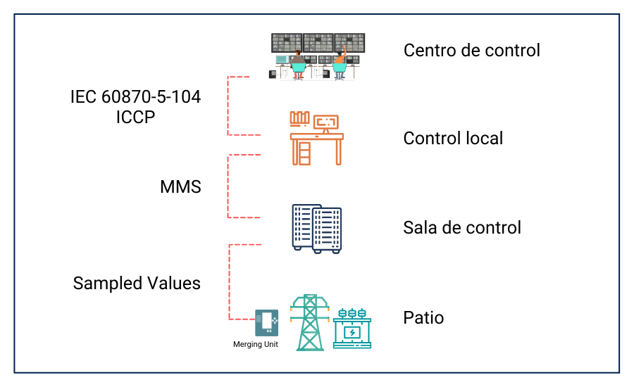
The synchrophasor communication protocol is designed so that technologies that process information from synchrophasors do not have to perform complex processes that delay the transmission of information. The main advantage of synchrophasor systems is their high real-time reporting rates of up to 60 messages per second, and that each transmitted message comes with an assigned timestamp thanks to the synchronization of the PMU with the GPS system. With these timestamps it is possible to identify the exact place and time when an event occurred on the power grid.
Article written by: Juan Carlos Vargas, Axon Group