A synchrophaser is a synchronized measurement of a signal that can be mathematically described as a phaser, i.e., a complex number or a double of magnitude and angle. In practice, the phasor measurement unit, or PMU, is the device that measures the waves in the electrical network and transmits them through a communications network, thus forming what is known as a synchrophasor network. Synchrophasor networks are systems oriented to data acquisition, supervision, monitoring and control in real time of the electrical network.
They are widely used in wide area electrical networks because each phasor measurement taken from the network is synchronized by a given timestamp according to UTC thanks to GPS technology. This allows us to see the state of the network in geographically distant places in the same instant of time in order to identify the exact place and moment in which an event occurred and take control actions to bring the system to normal operation conditions. Some of the applications of synchrophasor technology include wide area control, system model validation, determination of stability margins, maximization of stable system load, disturbance recording, visualization of dynamic system response, state estimation, among others.
Synchrophasor networks allow real-time analysis along the power system at high speeds, while a common SCADA delivers data every 5 or 10 seconds, measurement with synchrophasors delivers up to 60 datasets in one second. This information is sent to network operators who can see the status of the network in real time and prevent possible events that could affect its operation. In this way, operators can evaluate, diagnose, and implement techniques that protect the stability of the system.
History and Future of Synchrophaser Networks
In [1] reference is made to 3 outstanding inventions that made the development of synchrophasor technology possible. In 1893 the mathematician and engineer Charles Steinmetz published the article [2], which proposes the mathematical representation of an alternating current signal known today as a phasor. In 1973, the global positioning system, GPS, was invented, which allows the synchronization of data in a synchrophasor network. Finally, in 1979 A. Phadke of Virginia Tech University, developed the Symmetrical Component Distance Relay (SCDR). The SCDR was the basis for the development of synchrophasor networks because, with a unique algorithm based on the measurement of three-phase voltage and current signals in positive, negative and zero sequence, it could detect all types of faults. Based on these inventions, in 1988 Phadke and Throp developed the first prototype of a device that, from voltage and current signals, delivered synchronized measurements in real time known as Phasor Measurement Unit (PMU). In 1992 Macrodyne built the first commercial PMU.
By 2015 there were 1700 PMUs distributed throughout the US and Canadian power grids allowing almost 100% visibility of the power system in those countries. In Europe and Asia there are large scale projects focused on monitoring the power grid by means of synchrophasors. In Colombia, by 2014, XM’s ISAAC project had 44 PMU installed in 20 substations throughout the country [3].
In the future, this is expected to reduce the cost of devices to facilitate the implementation and maintenance of networks, increase security in communications, train personnel in the area since it is a recently implemented technology and is not usually treated in undergraduate courses, and increase investment in research and development. It is expected that synchrophasor technology will be widely used in the implementation of intelligent power networks since synchrophasor systems collect, distribute and analyze critical data and convert it into real time information that can greatly improve the operation and intelligent automation of the network.
Applications of Synchrophasor Technology in electrical power distribution networks
As mentioned before, synchrophasors are phasorial voltage and current measurements made at the same instant of time at different points of an electrical power system. These readings allow the development of different types of applications and their main objective is to improve the stability of the electrical network.
Protection and control applications based on synchrophasors are characterized by the increase in the effectiveness of the protections and the simplification of the mathematics used to estimate the system’s state, allowing the optimization of control schemes and reducing their uncertainty [4].
Status Estimates
The phasorial data of certain nodes of a power system are taken to a control center, where, by means of mathematical techniques, it is possible to estimate the voltage and current phasors (states) of all the nodes of the system, that is to say, the status of all the bars is estimated from the synchronized measurements of certain points of the power system. This allows the state of an electrical network to be monitored online and actions to be taken to prevent collapse due to loss of stability.
Surge Control
In high voltage lines, it is common to encounter overvoltage problems due to the capacitive effect of the circuits, which becomes more critical in conditions of minimum power demand. A synchronized voltage measurement allows establishing a voltage profile of an electrical power system and taking control actions such as removing circuits or connecting reactive compensation banks, to control surges and bring the system to an optimal operating state.
Load Shedding
With synchronized voltage measurements, slow and fast voltage collapses can be detected. Depending on the magnitude of the event, automatic actions are taken to de-ballast the sufficient amount of load to ensure a restoration of the voltage.
Angular Stability
In this application, the angular difference between various bars of the power system is monitored. If excessive angles are found that could affect stability, actions such as tripping circuits or isolating the system under fault are taken.
Thermal monitoring of transmission lines
The load that a transmission line can handle is restricted by its thermal limits even more than by voltage stability, since electrical resistance varies with temperature. With the data of magnitude and angle of the voltage at the connection nodes of the transmission line, and the angle of the current flowing through it, its series impedance and therefore its temperature can be determined. In this way, alarms can be generated in case of overloads or dynamic control of the line capacity can be exercised.
Voltage Instability
The growth in demand on the electricity networks increases the risk of violating network stability limits. In order to prevent a collapse, it is necessary to know the configuration of the network, the power flows and the voltages in its nodes. Synchrophasors can provide this key information and also facilitate the calculation of some indexes used for instability prediction. Additionally, with the synchrophasor technology, the speed of reaction to contingencies is increased since PMU’s present the system’s state without involving heavy data processing and the time stamps guarantee that the measurements belong to the same system’s state.
Advanced control schemes
Synchrophasors would allow the network controller to take the measurements of the system state vector directly, thus eliminating the uncertainty in the control loop inherent in the mathematical model. This way the controller is mainly based on feedback and less on models [5].
Distributed Generation Control
According to the IEEE, distributed generation is electrical energy produced by smaller facilities than the current large generation plants, so that they can be connected at any point in the electrical system. In this context, island status is an electrical phenomenon that occurs when the energy supplied by the electricity grid is interrupted and the distributed generators continue to power part or all of the load [6]. Figure 1 shows a typical network configuration for DG in which the opening of the B1 switch results in an island condition. During this island condition, AC machines are vulnerable to out-of-phase closures, which can cause permanent damage. Failure to trip isolated generators can represent a safety risk to personnel in the facility and can also result in power quality problems with connected loads. For these reasons, power utilities require that isolated distributed generators be disconnected as quickly as possible to minimize hazardous operating conditions [7].
Figure 1 shows a system with a relay, which has PMU functional modules, at the isolated generator location and another relay at a transmission substation. Both relays acquire voltage phasor measurements from both locations. These relays send synchro messages to the Synchro Vector Processor (SVP), a device that combines the functionality of a PDC with the features of a PLC allowing control schemes to be implemented, at specific time intervals (sixty messages per second, for example). The SVP uses the positive sequence voltage synchrophasors obtained from the relays to detect the island condition.

Event Detection
La figura 2 muestra una señal que contiene la
Figure 2 shows a signal that contains the response of the electrical power system to typical events, each dynamic at a different time scale. Some of the typical dynamic phenomena of an electrical system that can be identified from different components of the signals delivered by a PMU are:
- Discrete events such as switching transmission lines. Milliseconds.
- Small signal stability. Seconds.
- Transformer tap changing operation. Voltage stability.
Identifying these events allows the system operator to take appropriate action in a timely manner. Depending on the nature of these events, the actions can be preventative, corrective or restorative. Therefore, it is very important that the synchrophasor applications that detect these events are provided with clean information so that no false actions are taken.

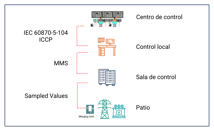
Components of a Synchrophasor Network
Within a network of synchrophasors, like the one in Figure 3, we can identify two main components, the phasor measurement units (or PMU) and the phasor data concentrators (or PDC). PMUs are devices that measure and deliver voltage and current, system frequency, rate of change of frequency (ROCOF), a time stamp, and the metadata needed to interpret the information. The PDCs act as nodes in the communication network where data from synchrophasors from different PMUs or other PDCs is processed and sent as a data stream to a higher level PDC. Some functions of the PDCs can be: performing data quality checks, data storage for later analysis and data visualization, among others.
The IEEE standard defines two classes of performance for PMU, class P which offers a fast response and less filtering, generally used for Protection applications, and class M which offers a slower response, but offers greater accuracy due to its strict filtering, generally used for data analysis.
We can talk about a hierarchical structure of PDCs that follows the hierarchy of power systems: substations, energy companies, regional control areas and interconnection level. The PDCs can also work one by one (peer to peer), when they are at the same level.

Messages in a Synchrophasor Network
The IEEE Std C37.118.2, Standard for Synchrophasor Data Transfer for Power Systems [8], defines four types of messages in a synchrophasor network.
- Data Message: These are the measures taken by the PMU: synchrophasors, frequency, ROCOF, analog and digital words.
- Configuration Message: Device configuration data, amount of PMU included in the data frame, data format, amount of signals and their names, scale factors and other metadata needed for information interpretation.
- Header Message: Descriptive information sent by the devices, but provided by the user. It is sent as ASCII characters.
- Command message: Sent by the devices to control communication. This type of message starts or ends data transmission and requests configuration and header frames.
The four types of message have the same basic structure:

SYNC: Synchronization word, two bytes that identify the beginning of a frame and the type of message.
FRAMESIZE: Number of bytes of the message, maximum 65,535 bytes.
IDCODE: Identifies the destination of the frame if it is a command message and the source if it is another type of message.
SOC: Time stamp, started on January 1, 1970 and restarted in 2016.
FRACSEC: Fraction of a second and quality time Measurement instant for data messages and transmission instant for other types of message.
CHK: Cyclic redundancy check. It serves to determine the integrity of the frame.
Bandwidth and Storage Considerations
The IEEE C37.118 protocol is efficient in terms of data format, however, certain considerations must be made regarding data transmission and storage. At a transmission rate of 60 frames per second, voltage and current phasors, frequency, ROCOF, analog and digital words, and time stamps, represent a large amount of information. For example, a PMU transmitting 8 phasors, 2 analog and 2 digital data, all at 60 messages per second floating point requires 61.2 kbps on serial port, 84.375 kbps on TCP and 78.75 kbps on UDP. This is a problem in the case of serial communication since a typical PMU serial port supports a bandwidth of 57.6 kbps [9].
Ideally there should be a PDC at each substation and at each checkpoint. This would reduce the necessary bandwidth of the communication channel to send the PMU information out of the substation since the PDC concentrates the data from all PMUs before sending it. In addition, it would improve security because only one data flow would have to be handled at one point in the substation.
Tables 1 and 2 show the bandwidth and storage requirements, useful in applications such as post failure analysis or event prediction, for 10 PMU similar to those in the example mentioned above.
The data format, reporting rate, and number of phasors must be determined by the application. If an application can function properly at a rate of 20 messages per second and format in integers, sending 60 messages per second in floating point would represent an unnecessary waste of bandwidth and storage capacity of 600%.
Data Flow | Bandwidth (kbps) | |
TCP | UDP | |
Individual by PMU | 650 | 600 |
United in a PDC | 260 | 254 |
Table 1. Effect of a PDC on the bandwidth.
Data Format | Storage | |||
Time | Day | Month | Year | |
Floating Point | 177 MB | 4.3 GB | 124 GB | 1.5 TB |
16-Bit Integer | 94 MB | 2.3 GB | 67 GB | 810 GB |
Table 2. Effect of formatting on storage space.
Many operators are currently improving their communication networks to allow the implementation of synchrophasor networks, however, by using the bandwidth offered by a switched network, a system can be configured to allow the use of this technology [10].
Referencias Bibliográficas
[1] Justin Beau, C. Blalock, E. Frye, F. Harley, C. Odom, H. Lu and J. Zhao,” An Introduction to Synchrophasors”.
[2] Charles Steinmetz, “Complex Quantities and Their Use in Electrical Engineering”.
[3] XM: Planeación y operación del SIN, “Proyectos para la planeación y operación confiable y segura del SIN”, 2015.
[4] Andrés Pérez, “Sincrofasores y su aplicación en control de área amplia en sistemas de potencia”, Universidad Autónoma de Occidente, 2012.
[5] XM: Cesar Augusto Giraldo García, “Unidad de Medición Fasorial Sincronizada PMUs”, 2009.
[6] David Velasco, César Trujillo, Johann Hernández, “Algoritmo de detección en modo isla de un inversor, basado en la medición del segundo armónico”, Universidad Distrital Francisco José de Caldas, 2012.
[7] Armando Guzman, Venkat Mynam, “Detección de condición de isla para la generación distribuida”, SEL, 2016.
[8] IEEE: “IEEE Standard for Synchrophasor Data Transfer for Power Systems”, 2011.
[9] Greg Hataway, Bill Flerchinger, Roy Moxley,” Synchrophasors for Distribution Applications”.
[10] SEL: “Synchrophasors FAQs”, 2012.
Artículo redactado por: Juan Carlos Vargas, Axon Group